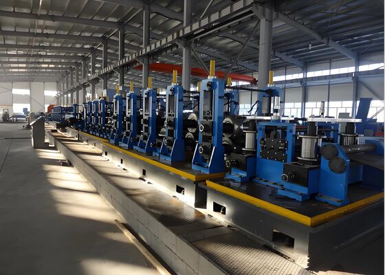
गोल स्टील पाइप बनाने के लिए रोलर बनाने की मशीन जिसकी दीवार की मोटाई 2 मीटर से 6 मीटर तक है
प्रसंस्करण रेंज:
गोल पाइप उत्पादन रेंज: φ60-φ165mm
चौकोर पाइप उत्पादन रेंज: 50×50-125×125mm
आयताकार पाइप उत्पादन रेंज: 40×60-150×100mm
दीवार की मोटाई: 2.0-6.0mm (गोल पाइप), 2.0-5.5mm (चौकोर पाइप)
उत्पाद अवलोकन:
यह लाइन मुख्य रूप से 60 से 165 मिमी व्यास और 2.0 से 6.0 मिमी की दीवार की मोटाई वाले इलेक्ट्रिक-वेल्डेड स्टील पाइपों के उत्पादन के लिए डिज़ाइन की गई है। यह गोल पाइपों की सीमा के भीतर चौकोर, आयताकार और विशेष आकार के पाइपों का भी उत्पादन कर सकती है। आवश्यक उपकरण जोड़कर, यह बाद में एपीआई 5एल पाइप का उत्पादन कर सकती है। इस उत्पादन लाइन को घरेलू और अंतरराष्ट्रीय दोनों स्रोतों से समान उपकरणों को एकीकृत करके, मेरे देश की राष्ट्रीय परिस्थितियों को ध्यान में रखते हुए, और साहसिक नवाचार और उपयोगकर्ताओं के साथ व्यापक परामर्श के माध्यम से डिजाइन और निर्मित किया गया था। यह किफायती, विश्वसनीय और स्थिर संचालन का दावा करता है।
स्टील पाइप उत्पादन रेंज
| गोल पाइप |
φ60 - φ165mm |
| चौकोर पाइप |
50x50 - 125x125mm |
| आयताकार पाइप |
40x60 - 150x100mm |
| दीवार की मोटाई |
2.0 - 6.0mm (गोल पाइप), 2.0 - 5.5mm (चौकोर पाइप) |
उत्पादन प्रक्रिया:
अनकोइलिंग → सीधा करना, क्लैंपिंग और लेवलिंग → कतरनी और बट वेल्डिंग → लूपिंग → बनाने, उच्च-आवृत्ति वेल्डिंग, बाहरी बर्र हटाना, ऑनलाइन जिंक रीफिलिंग, कूलिंग, साइजिंग, रफ स्ट्रेटनिंग → फ्लाइंग सॉ लेंथ एडजस्टमेंट → निरीक्षण और संग्रह → पैकेजिंग → वजन → लेबलिंग → भंडारण

उपकरण प्रदर्शन:
इस हाइड्रोलिक प्रेस में चार प्रमुख प्रक्रिया चरण हैं: आंतरिक दीवार फ्लशिंग, चेन बेड कन्वेयर, दबाव परीक्षण केंद्र, खाली करने वाला उपकरण, हाइड्रोलिक सिस्टम और विद्युत प्रणाली।
1) फ्लशिंग सिस्टम: संरेखण और फ्लशिंग कार्यों को शामिल करता है। एक फीडर डिवाइस पाइपों को लोडिंग प्लेटफॉर्म से संरेखण स्टेशन तक मात्रात्मक रूप से फीड करता है। एक कम दबाव वाला सेंट्रीफ्यूगल पंप ताजे औद्योगिक पानी को खींचता है, जिसे विभिन्न वाल्वों के माध्यम से फ्लशिंग हेड से जोड़ा जाता है। यह पानी दबाव परीक्षण शुरू होने से पहले पाइप से अशुद्धियों को हटाता है ताकि उपकरण पर सील को नुकसान पहुंचाने वाली अवशिष्ट अशुद्धियों को रोका जा सके।
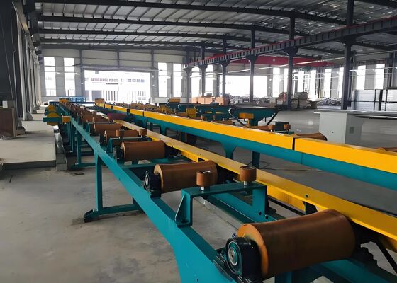
2) चेन बेड कन्वेयर मैकेनिज्म: दबाव-परीक्षण किए गए स्टील पाइपों के लिए कट-टू-लेंथ लंबाई की विस्तृत श्रृंखला को ध्यान में रखते हुए, चेन बेड कन्वेयर संरचना निम्नलिखित विन्यास को अपनाती है: चेन बेड मैकेनिज्म स्वतंत्र रूप से संचालित चेन बेड के दो सेटों से बना है। एक सेट को फिक्स्ड सीट के साथ बेस पर फिक्स किया गया है, जिससे उसकी गतिहीनता बनी रहती है। चेन बेड के किनारों पर सपोर्ट मैकेनिज्म स्थापित किए जाते हैं ताकि छोटे व्यास के स्टील पाइपों को चेन पर रखे जाने पर झुकने से रोका जा सके। चेन बेड का एक और सेट एक मूवेबल सीट (किनारों पर सपोर्ट मैकेनिज्म स्थापित के साथ) पर फिक्स किया गया है और विभिन्न कट-टू-लेंथ के स्टील पाइपों के उपयोग के अनुसार संबंधित स्थिति में चलता है, जिससे विभिन्न कट-टू-लेंथ स्टील पाइपों की दबाव-परीक्षण केंद्र तक सुचारू डिलीवरी सुनिश्चित होती है। यह संरचना चेन बेड और अन्य तंत्रों को अलग किए बिना विभिन्न कट-टू-लेंथ के स्टील पाइपों के दबाव परीक्षण की सुविधा प्रदान करती है।
3) डुअल-स्टेशन प्रेशर-टेस्टिंग सेंटर में एक फिक्स्ड सीट, एक मूवेबल सीट, एक फिक्स्ड बेस, एक प्रेशर टेस्ट हेड, एक क्लैंपिंग डिवाइस, एक लो-प्रेशर वॉटर सिस्टम, एक हाई-प्रेशर वॉटर सिस्टम और अन्य घटक शामिल हैं।
प्रेशर-टेस्ट मूवेबल सीट में एक सपोर्ट, एक मेन सिलेंडर मूविंग मैकेनिज्म, एक वाल्व बॉडी, एक लैच मैकेनिज्म, एक एग्जॉस्ट वाल्व बॉडी और एक मेन सिलेंडर मैकेनिज्म शामिल है। सपोर्ट एक वेल्डेड संरचना है जो मुख्य रूप से उपरोक्त घटकों का समर्थन करती है। मेन सिलेंडर मूविंग मैकेनिज्म में सिलेंडर 5 वाल्व बॉडी को आगे बढ़ाता है, जिससे पाइप का सिरा प्रेशर टेस्ट हेड असेंबली में प्रवेश कर पाता है। लैच मैकेनिज्म का उपयोग तब किया जाता है जब प्रेशर टेस्ट पाइप की लंबाई बदली जाती है। मूवेबल बेस को निर्दिष्ट लंबाई के अनुसार एक AC2.2kW मोटर द्वारा निर्दिष्ट स्थिति में ले जाया जाता है। लैच मैकेनिज्म मूवेबल बेस को पोजिशन करने के लिए फिक्स्ड बेस पर संबंधित स्थिति में एक बेलनाकार पिन डालता है। मेन प्रेशर टेस्ट सिलेंडर असेंबली पाइप की लंबाई बढ़ने पर संतुलित पानी और तेल के दबाव को बनाए रखती है। एग्जॉस्ट वाल्व बॉडी पाइप से हवा निकालती है जब पानी को पाइप की आंतरिक दीवार में फ्लश किया जाता है। एग्जॉस्ट के बाद, हवा सिलेंडर के माध्यम से निकल जाती है और वाल्व बॉडी बंद हो जाती है, जिससे स्थिर दबाव बनाए रखने वाले मान और अवधि सुनिश्चित होती है।
प्रेशर टेस्ट फिक्स्ड बेस में एक सपोर्ट, वाल्व बॉडी, वाटर फिलिंग वाल्व, सिलेंडर एडजस्टमेंट मैकेनिज्म और वाटर पाइपिंग सिस्टम शामिल है। मेन सिलेंडर एडजस्टमेंट मैकेनिज्म वाल्व बॉडी को एडजस्ट करने के लिए सिलेंडर का उपयोग करता है ताकि पाइप एंड फेस टेस्ट हेड में प्रवेश कर सके। वाटर फिलिंग वाल्व पाइप में कम दबाव वाले पानी के फ्लशिंग की अनुमति देने के लिए वाल्व बॉडी खोलता है और दबाव बढ़ाने और दबाव बनाए रखने के लिए वाल्व बॉडी बंद करता है। क्लैंपिंग डिवाइस में क्लैंपिंग मैकेनिज्म, रोलर्स, व्हील असेंबली और एक सपोर्ट शामिल है। क्लैंपिंग मैकेनिज्म को हाइड्रोलिक सिलेंडर द्वारा संचालित किया जाता है, जो स्टील पाइप को दोनों तरफ से क्लैंप करता है और सिंक्रोनस रूप से चलता है। रोलर असेंबली पाइप की लंबाई के अनुसार क्लैंपिंग मैकेनिज्म की स्थिति को एडजस्ट करती है। रोलर असेंबली को पाइप व्यास के अनुरूप ऊंचाई में एडजस्ट किया जा सकता है, यह सुनिश्चित करते हुए कि विभिन्न व्यास के पाइप हमेशा पानी के दबाव के केंद्र में हों।
टेस्ट हेड पॉलीयूरेथेन से बना एक रेडियल रूप से सील फिटिंग है। विभिन्न पाइप आकारों के लिए संबंधित सील के साथ सील को बदला जाता है। हाइड्रोलिक सिलेंडर-संचालित स्वचालित सेंट्रिंग क्लैंप पाइप के विभिन्न आकारों को समायोजित करने के लिए इंटरचेंजेबल सेंटर स्लिप की अनुमति देता है। यह उत्कृष्ट दबाव सीलिंग और लंबे समय तक सेवा जीवन सुनिश्चित करता है। तीन टेस्ट हेड असेंबली शामिल हैं: Φ60, Φ119, और Φ165। अन्य आकार अनुकूलित किए जा सकते हैं या ग्राहक द्वारा प्रदान किए जा सकते हैं।
पानी का दबाव प्रणाली एक कम दबाव वाले पानी इंजेक्शन प्रणाली और एक उच्च दबाव वाले पानी भरने की प्रणाली से बनी है। कम दबाव वाले पानी इंजेक्शन प्रणाली स्वचालित पानी की आपूर्ति के लिए एक एकल-चरण, एकल-सक्शन सेंट्रीफ्यूगल पंप का उपयोग करती है, जिसमें एक स्वचालित एयर वाल्व स्विचिंग फ़ंक्शन होता है। उच्च दबाव वाले पानी भरने की प्रणाली में एक उच्च दबाव वाला प्लंजर पंप, एक चेक वाल्व असेंबली और एक बायपास वाल्व सिस्टम शामिल है। यह रेडियल प्री-सील दबाव परीक्षण करता है और स्टील पाइप के भीतर आंतरिक दबाव बढ़ाता है। यह बड़े गैप सील को प्री-सील करने या परीक्षण दबाव के आधार पर सीधे दबाव बढ़ाने और बनाए रखने का कार्य करता है।
पानी निकालने वाले उपकरण में एक एयर ब्लोइंग डिवाइस, एक लिफ्टिंग डिवाइस और एक मटेरियल रिटेनिंग डिवाइस शामिल है। दबाव लागू होने के बाद, लिफ्टिंग डिवाइस स्टील पाइप को उठाता है, जिससे पाइप की दीवार के अंदर का पानी बाहर निकल जाता है। इस प्रक्रिया के दौरान, मटेरियल रिटेनिंग डिवाइस पाइप को लुढ़कने से रोकने के लिए जगह पर रखता है। एयर ब्लोइंग डिवाइस पाइप की दीवार से पानी और अन्य अशुद्धियों को हटाता है।
हाइड्रोलिक सिस्टम:
यह सिस्टम एक स्वतंत्र हाइड्रोलिक स्टेशन से बना है। हाइड्रोलिक तेल को हर छह महीने में बदला जाना चाहिए, और टैंक को मलबे से साफ किया जाना चाहिए और साफ तेल से फिर से भरा जाना चाहिए।
| कूलिंग विधि |
वाटर-कूल्ड मेन हाइड्रोलिक स्टेशन |
| कार्य दबाव |
8-10 MPa |
| परिसंचारी शीतलन जल दबाव |
0.4-0.6 MPa |
| कार्य माध्यम |
N46# एंटी-वियर हाइड्रोलिक ऑयल |
| सिस्टम स्वच्छता आवश्यकता |
NAS क्लास 16389 |
हाइड्रोलिक सिस्टम प्रदर्शन विशेषताएँ:
सिस्टम दबाव को क्षेत्र और उपयोग की आवश्यकताओं के अनुसार कॉन्फ़िगर किया गया है और यह पास में स्थित है।
हाइड्रोलिक स्टेशन टैंक में एक बाहरी हाइड्रोलिक तेल शीतलन प्रणाली और टैंक की ऊपरी सतह पर एक तेल संग्रह नाली है।
हाइड्रोलिक स्टेशन मैनिफोल्ड कनेक्शन का उपयोग करता है, और वाल्व घटक बीजिंग हुआडे हाइड्रोलिक्स से हैं।
हाइड्रोलिक स्टेशन एक तेल स्तर अलार्म प्रणाली से सुसज्जित है जो तेल स्तर एक निश्चित स्तर तक गिरने पर स्वचालित रूप से अलार्म बजाता है, जिससे टैंक में तेल स्तर बनाए रखा जाता है। पाइपिंग को साफ-सुथरा व्यवस्थित किया गया है, सुरक्षित है और आवश्यकताओं के अनुरूप है, जिससे यूनिट को अलग करना और पाइपिंग रखरखाव करना आसान हो जाता है।

 आपका संदेश 20-3,000 अक्षरों के बीच होना चाहिए!